
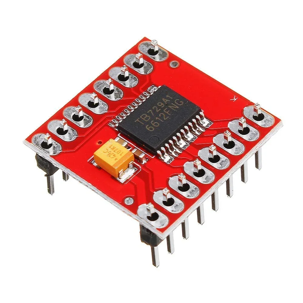
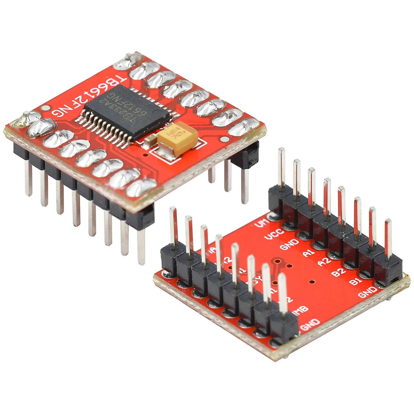
Description
The TB6612FNG Dual Motor Driver Module uses two built-in H-bridge circuits to independently control two brushed DC motors. It supports PWM speed control and provides forward, reverse, brake, and stop operation.
The module also includes standby/power-saving functionality, thermal shutdown protection, low-voltage detection, and a low ON-resistance MOSFET output stage for efficient motor control. It can be controlled by Arduino, Raspberry Pi, ESP32, and other microcontroller platforms.
Specifications
- Model: TB6612FNG
- Driver Type: Dual H-Bridge DC Motor Driver
- Number of Motors: 2 DC Motors
- Motor Supply (VM): Up to 15V maximum
- Average Output Current: 1.2A per channel
- Peak Output Current: 3.2A peak
- Control Logic: Microcontroller-compatible logic inputs
- Motor Control: Forward / Reverse / Brake / Stop
- Speed Control: PWM
- Standby Function: Yes
- Protection: Thermal shutdown and low-voltage detection
- IC Package: Toshiba SSOP24
- Motor Type: Brushed DC Motor
- Applications: Arduino, robotics, RC projects, automation
Key Features
- Dual motor control — independently controls two DC motors.
- 1.2A average output per channel according to the TB6612FNG specification.
- PWM speed control for variable motor speed.
- Forward and reverse operation using H-bridge control.
- Short-brake function for rapid motor stopping.
- Standby/power-save mode reduces power consumption when the driver is not being used.
- Thermal shutdown protection helps protect the IC against excessive temperature.
- Low-voltage detection provides additional protection.
- Low ON-resistance MOSFET output stage for improved efficiency.
- Compact design suitable for Arduino and other microcontroller projects.
How It Works
Dual Channel: The module can independently control two DC motors or control one bipolar stepper motor.
Full Control: Each motor can be driven forward or backward, electrically braked, or allowed to coast.
Speed Adjustments: PWM signals from a microcontroller can be used to adjust the motor speed.
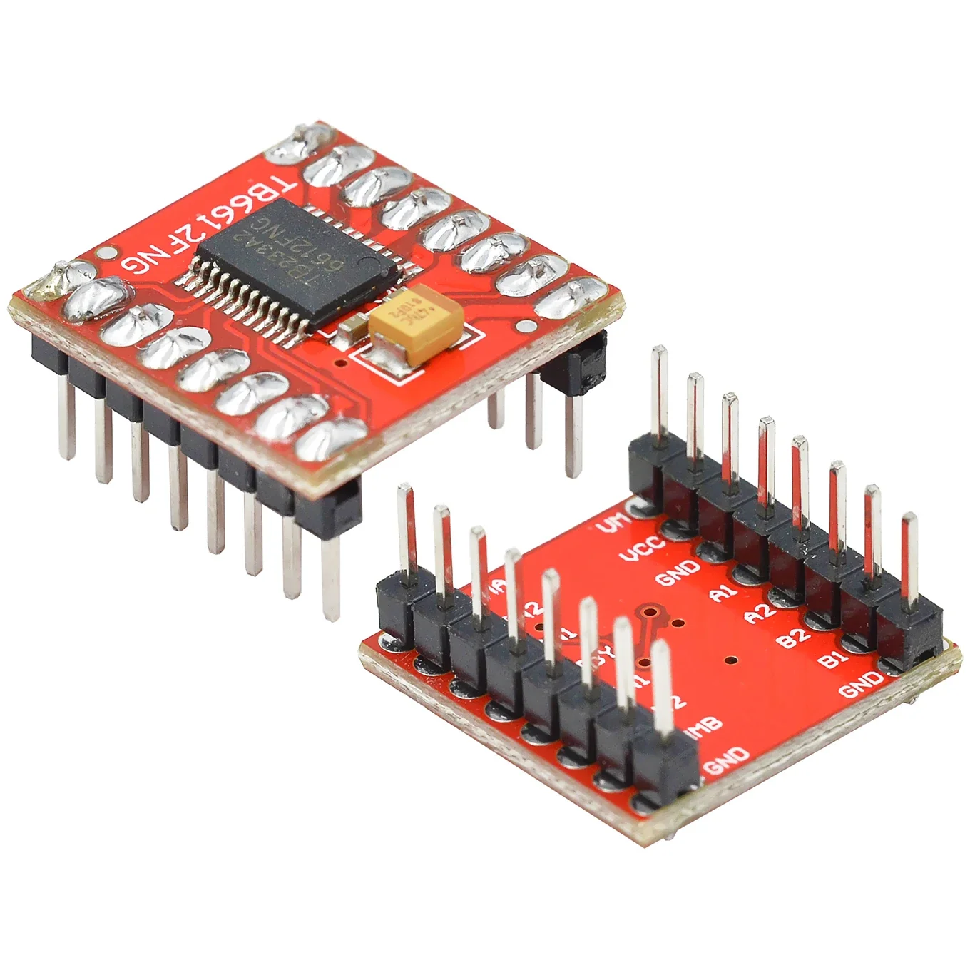
Pinout and Connection Guide
Power and Motor Pins
- VM: Motor power input, connected to the motor battery or power supply.
- VCC: Logic power input, compatible with 5V or 3.3V microcontroller logic.
- GND: Ground connection shared by the microcontroller and motor power supply.
- AO1 / AO2: Output pins for Motor A.
- BO1 / BO2: Output pins for Motor B.
Logic Control Pins
- PWMA: PWM speed control for Motor A.
- AIN1 / AIN2: Direction control for Motor A.
- STBY: Standby control pin; set HIGH to enable the driver.
- BIN1 / BIN2: Direction control for Motor B.
- PWMB: PWM speed control for Motor B.
Truth Table
| AIN1 / BIN1 | AIN2 / BIN2 | Motor Behavior |
|---|---|---|
| LOW | LOW | Coast — motor stops gradually |
| HIGH | LOW | Forward rotation |
| LOW | HIGH | Reverse rotation |
| HIGH | HIGH | Brake — motor stops quickly |

Reviews
There are no reviews yet.